DBC Substrates for Thick-Film Hybrid Circuits
Ceramic Substrate
SKU: FWM/CS-DBC-003
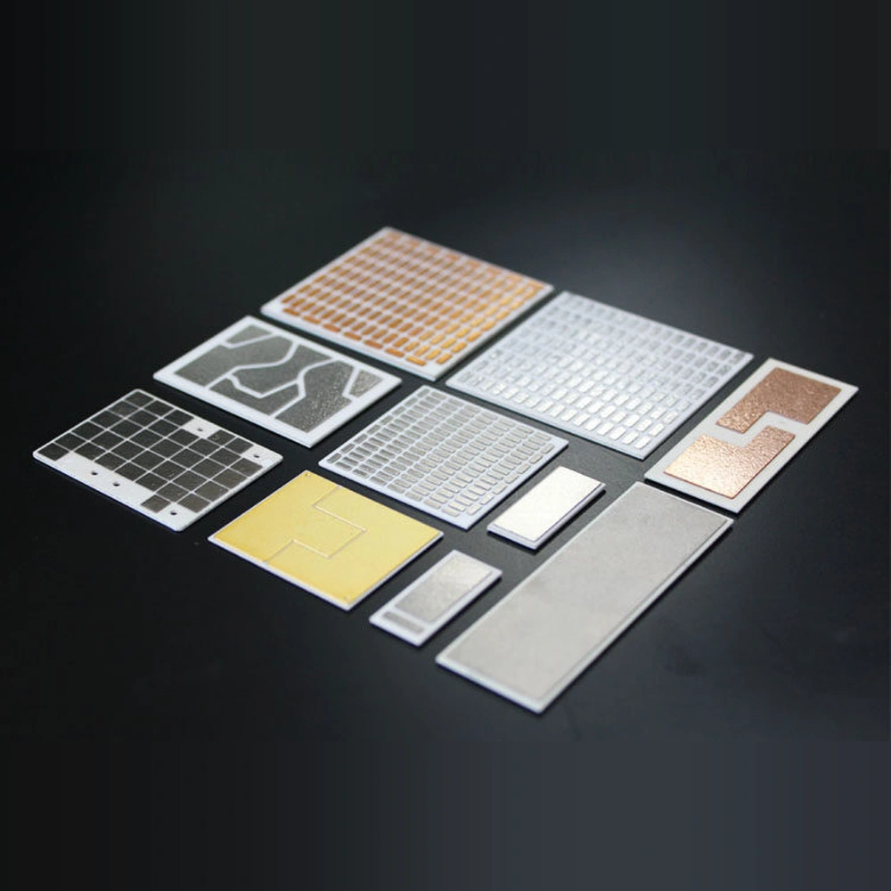
- Material
- Ceramic / Direct-Bonded Copper System
- Size
- Custom sizes by drawing
- MOQ
- 5 pieces or one master-card equivalent
- Applications
- Thick-Film Power Circuits
DBC substrates for thick-film power circuits requiring robust bonded copper and electrical insulation.
Browse Products
Alumina Ceramic Products
Zirconia Ceramic Products
Silicon Carbide Products
Silicon Nitride Products
Aluminum Nitride Products
Product Description

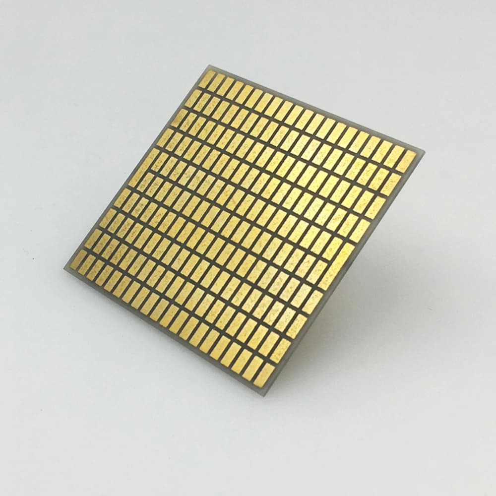
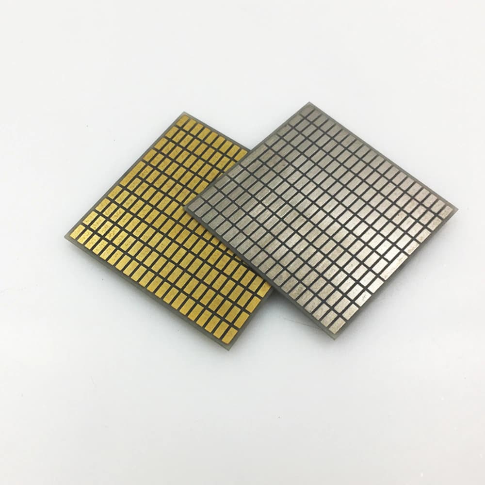
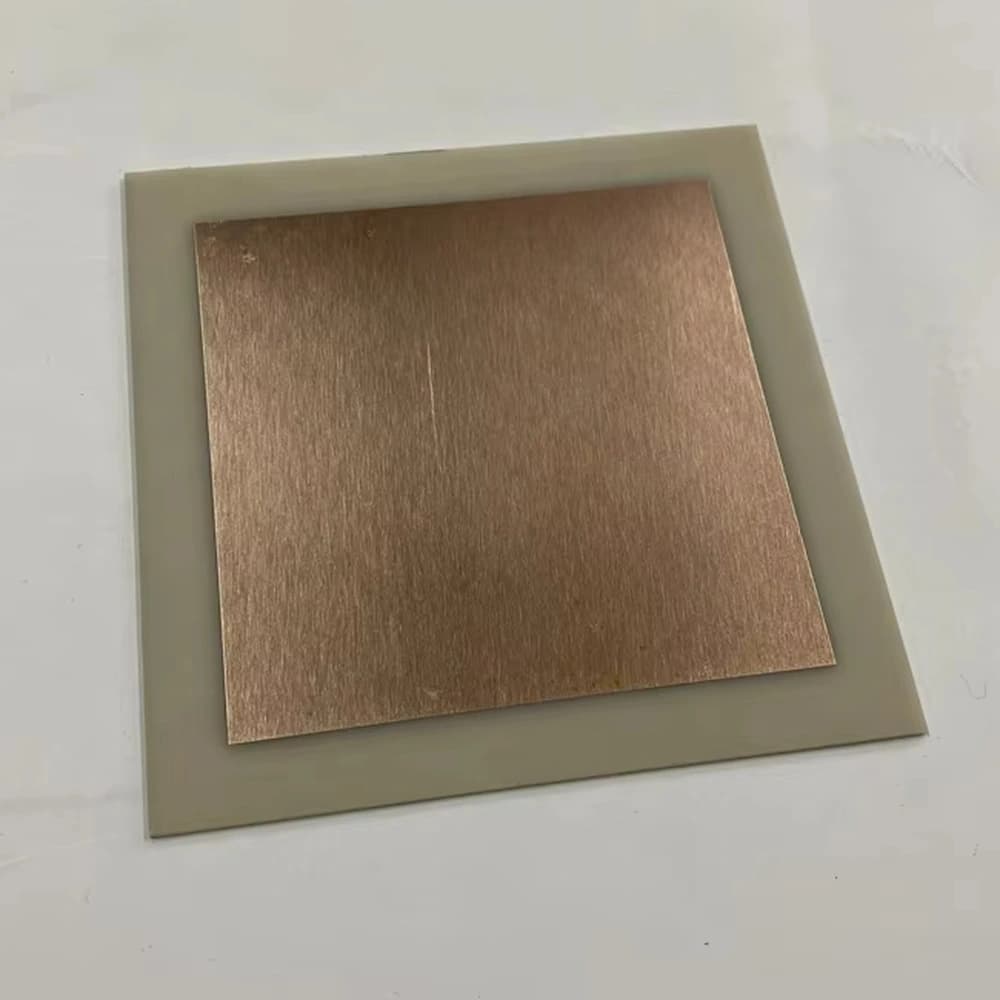
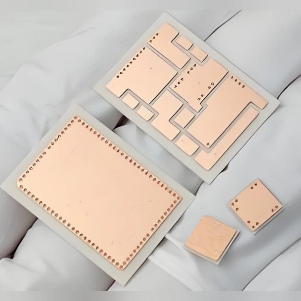
DBC substrates provide bonded copper conductors on an insulating ceramic carrier for power and hybrid circuit assemblies.
The copper foil carries current and spreads heat. DBC bonding is distinct from printing and firing thick-film materials; constructions combining them require compatible downstream processing.
DBC copper bonding is not the same process as screen-printed thick-film circuitry. Confirm which conductor system and downstream processing the application requires.
Product Advantages
- Bonded copper foil provides current paths and heat spreading on ceramic.
- The insulating base supports hybrid assemblies that combine different circuit elements.
- Copper patterns supply attachment areas alongside compatible downstream processing.
Typical Applications
- Thick-Film Power Circuits: DBC copper carriers support power components and compatible functional layers.
- Hybrid Electronics: bonded conductors provide electrical paths over ceramic insulation.
Technical Data
96% Alumina Substrate (708 S) Properties
| Property | 96% Al₂O₃ — 708 S | Test conditions / measurement tolerance ±10% |
|---|---|---|
| Density (g/cm³) | ≥3.75 | DIN EN 993-1 |
| Bending strength, σ₀ (MPa) | ≥500 | — |
| Young’s modulus (GPa) | ≥300 | — |
| Thermal conductivity (W/(m·K)) | 24 | Room temperature; DIN EN 821-2 |
| Linear thermal expansion coefficient (10⁻⁶/K) | 7–9 | 100–800°C; DIN 51045-1 |
| Specific heat capacity (J/(g·K)) | ≥0.75 | 20°C; DIN EN 821-3 method B |
| Relative permittivity | ~9.8 | Room temperature, 1 MHz; Ra ≤0.4 µm |
| Dielectric loss factor | ≤0.005 | Room temperature; 1 MHz; Ra ≤0.4 µm |
| Volume resistivity (Ω·cm) | ≥10¹⁴ | Room temperature; IEC 62631-3 |
| Breakdown strength (kV/mm) | AC≥15; DC≥15 | 20°C; AC / DC |
| Fracture toughness (MPa·m½) | ≥3.0 | Indentation-fracture (IF) |
95% AlN Substrate Properties
| Property | 95% AlN typical value | Condition / method |
|---|---|---|
| AlN content (%) | 95 | — |
| Density (g/cm³) | ≥3.3 | — |
| Flexural strength (MPa) | ≥400 | — |
| Thermal conductivity (W/(m·K)) | ≥170 | Room temperature |
| Relative permittivity | 8–10 | 1 MHz; room temperature |
| Dielectric loss tangent | ≤0.0003 | 1 MHz; room temperature |
| Dielectric strength (kV/mm) | 17 | — |
| Volume resistivity (Ω·cm) | ≥10¹⁴ | — |
Typical Construction Parameters
| Construction item | Typical configuration | Applicable condition |
|---|---|---|
| Ceramic base | 96% Al2O3 or AlN | Route dependent |
| Ceramic thickness | Alumina: 0.25–1.00 mm; AlN: 0.25–1.50 mm | Matched ceramic / copper stack |
| Copper thickness | 0.10–0.30 mm | Copper thickness and ceramic stack selected together |
| Line / space | Etched-pattern dependent | Copper thickness, etch profile and insulation clearance |
| Surface finish | Bare/protected Cu; selected Ni, Ni/Au or Ag | Assembly-process dependent |
| Bond / peel testing | Construction-specific test | Peel method, coupon geometry and acceptance criterion |
How to Read the Parameters
- Copper thickness
Foil thickness influences conductor cross-section and etched geometry.
Specify: Finished thickness, sidewall/gap requirements and patterning rules.
- Ceramic conductivity
W/(m·K) describes the ceramic at stated conditions.
Specify: Grade and temperature; keep separate from finished thermal resistance.
- Flatness and copper balance
Incoming ceramic shape does not establish the finished bonded shape.
Specify: Top/bottom pattern, copper-free perimeter and inspection condition.
- Dielectric performance
Material breakdown strength in kV/mm is not an assembly working-voltage rating.
Specify: Stack, gaps, edge clearances, waveform and test conditions.
DBC: bonded copper foil for power circuits
DBC uses a copper–oxygen eutectic interfacial reaction at elevated temperature to join copper foil to a ceramic surface. Conventional AlN DBC includes controlled oxide-surface preparation because AlN is a non-oxide ceramic. The bonded foil is then patterned; it is distinct from printed and fired thick-film conductors or resistors.

Application Conditions & Design Review
Separate bonded copper from printed films
DBC provides bonded copper conductors. A hybrid circuit may also contain printed resistor or dielectric films, but those films require their own compatible materials and processing sequence.
Review the exposure of the finished copper
If printing or firing follows DBC fabrication, account for the temperature, atmosphere and chemistry seen by copper and any surface finish. Compatibility must be established for the actual sequence.
Current and geometry
Choose copper thickness with conductor width, spacing and patterning feasibility.
Thermal and mechanical balance
Review ceramic thickness, copper distribution and the completed heat path together.
Hybrid integration
If printed films are needed, define their function and compatibility separately from the bonded copper.
Send With Your Drawing
- DBC ceramic/copper stack, artwork and supplied surface finish.
- Printed-film materials, layer locations and drying/firing sequence.
- Assembly exposure and functional/electrical acceptance requirements.
Include the drawing revision, sample and production quantities, and required inspection documents.
Define Acceptance Before Production
- Inspect the DBC pattern and interfaces before downstream film processing.
- Qualify film adhesion, electrical behavior and insulation after the complete process sequence.
Agree the test methods, sampling plan, acceptance limits and required reports before production.
Available Forms & Processing
Product-specific geometry and processing features.
- Copper foil thickness, etched pattern and selected ceramic grade defined together.
- Any printed or fired functional layers specified separately from DBC bonding.
- Surface finish and downstream thermal sequence coordinated with the copper construction.
Engineering Questions
Is thick copper the same as a thick-film printed circuit?
No. Thick copper describes the conductor construction; thick-film circuitry is formed from printed and fired functional materials. They can be combined only through a compatible, specified process.
Is DBC just copper mechanically attached to ceramic?
No. DBC is a controlled high-temperature bonding technology, not merely mechanical attachment.
Why must copper thickness and circuit spacing be reviewed together?
Thicker copper changes the conductor cross-section and etched sidewall geometry. Confirm finished track width, isolation gap and edge clearances for the selected thickness rather than applying one spacing rule to every stack.
Packaging & Shipping
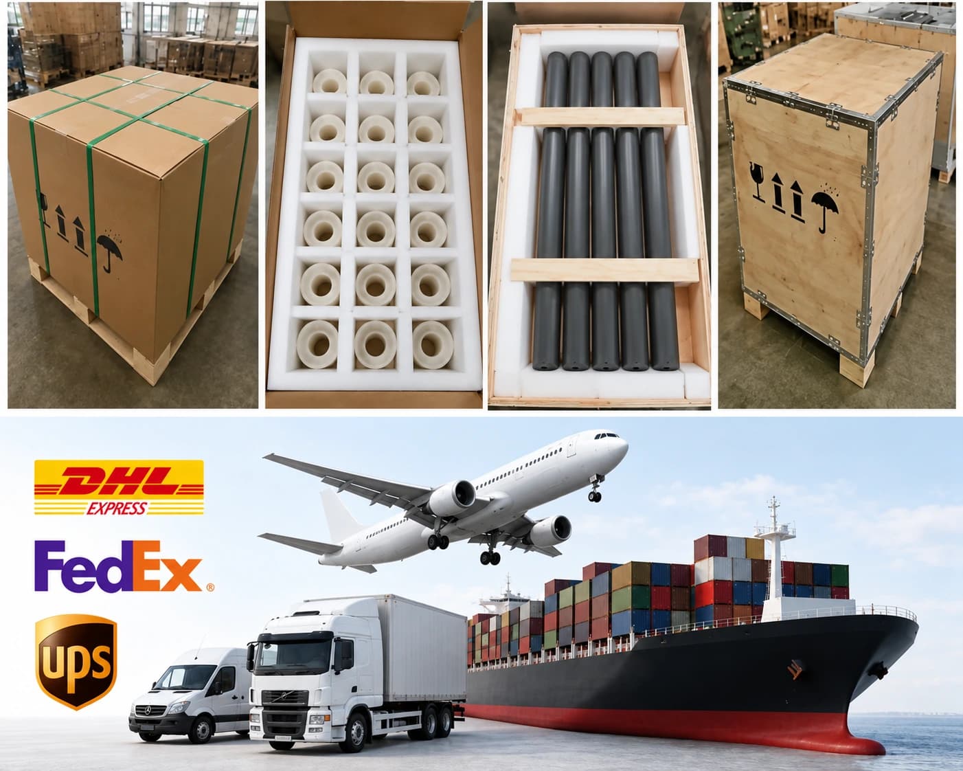
Packaging is selected for master cards, individual units and copper surface condition.
| Item | Details |
|---|---|
| Packaging approach | Packaging is selected for master cards, individual units and copper surface condition. |
| Protection methods | Individual separation; Anti-scratch surface protection; Rigid trays or master-card frames; Copper corrosion protection where appropriate; Inner box and export carton; Wooden case when required |
| MOQ reference | 5 pieces or one master-card equivalent |
| Lead-time references | DBC: 5-9 weeks |
| Payment terms | T/T / Western Union / PayPal; 50% advance payment, 50% balance before shipment |
| Shipping methods | Sea freight / Air freight / Door-to-door courier |
Related Ceramic Substrate Products
Compare related ceramic substrate materials and metallization routes within the same product family.