Ceramic Feedthroughs
Metallized Ceramics Component
SKU: FWM/MET-FT-001
- Material
- Metallized Ceramic Family
- Size
- Custom sizes available
- MOQ
- Pending Verification
- Applications
- Vacuum Equipment
Ceramic insulating feedthrough bodies and components for electrical, vacuum and hermetic assembly designs.
Browse Products
Alumina Ceramic Products
Zirconia Ceramic Products
Silicon Carbide Products
Silicon Nitride Products
Aluminum Nitride Products
Product Description
Ceramic insulating feedthrough bodies and components for electrical, vacuum and hermetic assembly designs.
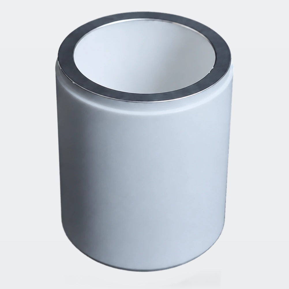
Ceramic feedthroughs isolate an electrical conductor from a housing while supporting an application-specific sealed or brazed assembly. The ceramic body is one component of a feedthrough, not a complete hermetic assembly.
The ceramic body provides electrical separation at the housing penetration; its joining surfaces connect the insulating body to the surrounding metal assembly.
Product Features
- Electrical Isolation
- Ceramic-to-Metal Interface
- Hermetic Assembly Potential
- Custom Conductor Geometry
Typical Applications
- Vacuum Equipment — Electrical feedthrough and sensor assemblies: Supports an insulating passage through a controlled boundary.
- Sensors and Instrumentation — Connector and signal feedthrough assemblies: Provides ceramic isolation and joining surfaces after design review.
Product Geometry & Configuration
Alumina Typical Material Properties
| Property | 95% Al₂O₃ | 99% Al₂O₃ | 99.5% Al₂O₃ | 99.8% Al₂O₃ | Condition / basis |
|---|---|---|---|---|---|
| Density (g/cm³) | 3.65 | 3.85 | 3.90 | 3.92 | — |
| Fracture toughness (MPa·m½) | 3–4 | 3–4 | 4 | 4 | — |
| Young’s modulus (GPa) | 320 | 340 | 370 | 390 | — |
| Flexural strength (MPa) | 300 | 330 | 375 | 390 | 25°C |
| Compressive strength (MPa) | 2200 | 2350 | 2450 | 2500 | 25°C |
| Thermal conductivity (W/(m·K)) | 18–22 | 27 | 29 | 32 | 25°C |
| Linear thermal expansion coefficient (10⁻⁶/K) | 8 | 8 | 8 | 8 | 25–1000°C |
| Dielectric strength (kV/mm) | 16 | 20 | 22 | 22 | — |
| Volume resistivity (Ω·cm) | 10¹⁴ | 10¹⁴ | 10¹⁴ | 10¹⁴ | 25°C |
| Relative permittivity | 9 | 9.7 | 9.7 | 9.8 | 1MHz, 25°C |
| Dielectric loss | 0.0004 | 0.0002 | 0.0002 | 0.0001 | 1MHz, 25°C |
| Vickers hardness (HV) | >1300 | 1700 | 1750 | 1800 | — |
| Material thermal-shock temperature difference, ΔT (°C) | 220 | 180–200 | 180–200 | 180–200 | — |
| Typical maximum material temperature (°C) | 1500 | 1650 | 1700 | 1700 | — |
AlN (AN216A) Typical Properties
| Property | AN216A typical value | Condition / method |
|---|---|---|
| Density | 3.4 g/cm³ | JIS R 1634 |
| Water absorption | 0 % | JIS C 2141 |
| Vickers hardness | 10.4 GPa | HV9.807N (9.807 N load); JIS R 1610 |
| Three-point flexural strength | 310 MPa | Three-point bending; JIS R 1601 |
| Young’s modulus | 320 GPa | JIS R 1602 |
| Poisson’s ratio | 0.24 | JIS R 1602 |
| Fracture toughness (SEPB) | 3.2 MPa·m½ | SEPB; JIS R 1607 |
| Linear thermal expansion, 40–400°C | 4.6 × 10⁻⁶/K | 40–400°C; JIS R 1618 |
| Linear thermal expansion, 40–800°C | 5.3 × 10⁻⁶/K | 40–800°C; JIS R 1618 |
| Thermal conductivity | 150 W/(m·K) | 20°C; JIS R 1611 |
| Specific heat capacity | 0.71 J/(g·K) | JIS R 1611 |
| Material thermal-shock temperature difference | 250 °C | Water immersion; relative method; JIS R 1648 |
| Dielectric strength | 14 kV/mm | JIS C 2141 |
| Volume resistivity, 20°C | >10¹⁴ Ω·cm | 20°C; JIS C 2141 |
| Volume resistivity, 300°C | 10¹⁰ Ω·cm | 300°C; JIS C 2141 |
| Volume resistivity, 500°C | 10⁸ Ω·cm | 500°C; JIS C 2141 |
| Relative permittivity | 8.6 | 1 MHz; JIS C 2141 |
| Dielectric loss tangent | 0.0003 | 1 MHz; JIS C 2141 |
Product Geometry & Configuration
| Product parameter | Configuration | Basis |
|---|---|---|
| Material system | Metallized Ceramic Family | Material family; grade selected for the application |
| Component forms | Single-channel ceramic bodies; Multi-channel feedthrough bodies; Custom flanged or tubular components | Drawing-defined configurations |
| Geometry and dimensions | Custom sizes available | Part drawing and mating interfaces |
| Functional surfaces | Contact, locating, joining or insulating surfaces as applicable | Surface finish and acceptance criteria on the drawing |
Available Forms
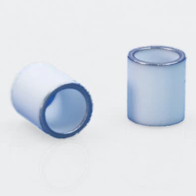
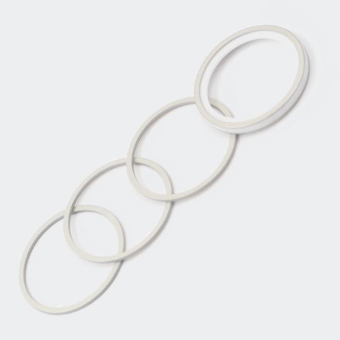
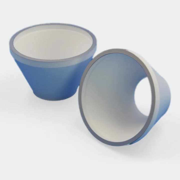
Representative forms are shown for selection. Final geometry, material route, interface, finish and acceptance criteria require drawing review.
- Single-channel ceramic bodies
- Multi-channel feedthrough bodies
- Custom flanged or tubular components
Packaging & Shipping
Packing and shipment arrangements are selected for the confirmed component geometry and surface requirements.
| Item | Details |
|---|---|
| Product protection | Selected for geometry, surface condition and quantity |
| Other commercial terms and lead time | Confirmed in quotation |
| Source boundary | No competitor packaging or delivery promise is inherited. |
| Payment terms | T/T / Western Union / PayPal; 50% advance payment, 50% balance before shipment |
| Shipping methods | Sea freight / Air freight / Door-to-door courier |

Related Metallized Ceramics Products
Explore related products within the same canonical family.