Silicon Nitride AMB Copper-Clad Substrates
Ceramic Substrate
SKU: FWM/CS-AMB-004
- Material
- Ceramic / Copper AMB System
- Size
- Custom sizes by drawing
- MOQ
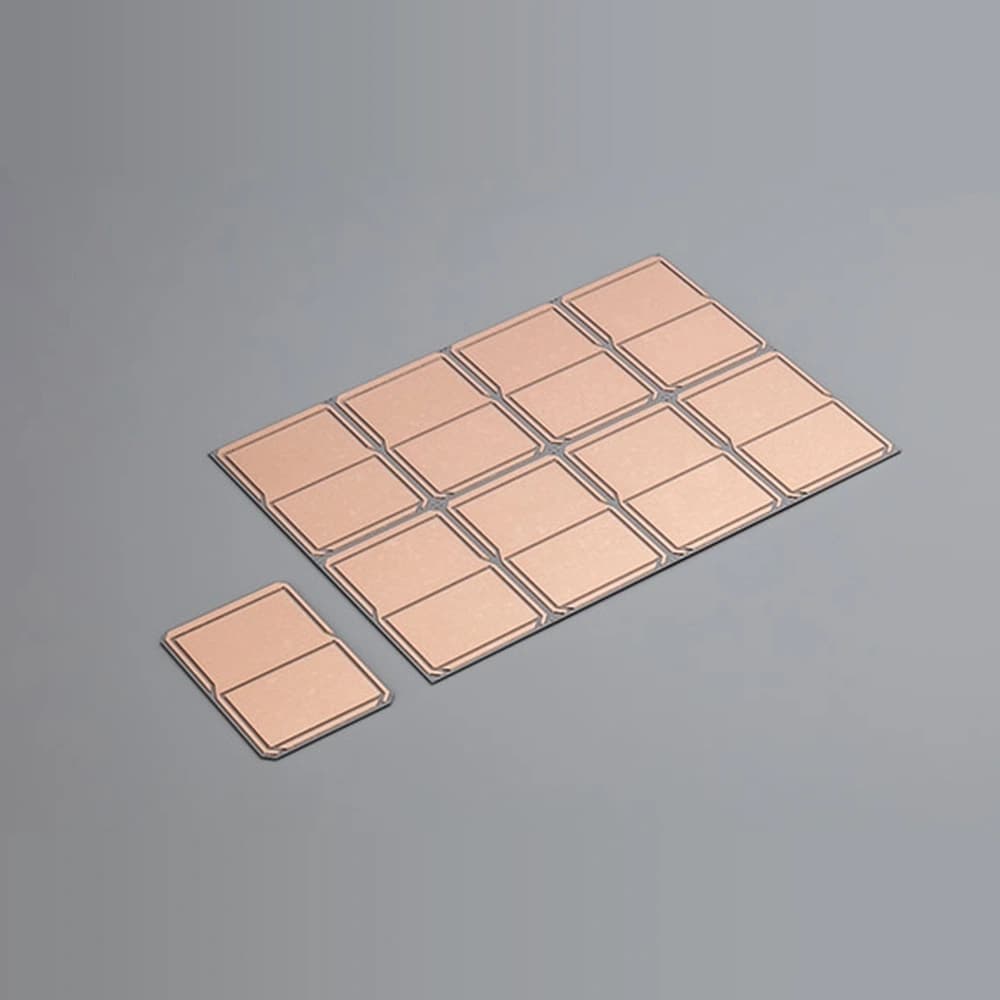
- 5 pieces or one master-card equivalent
- Applications
- Automotive Inverters
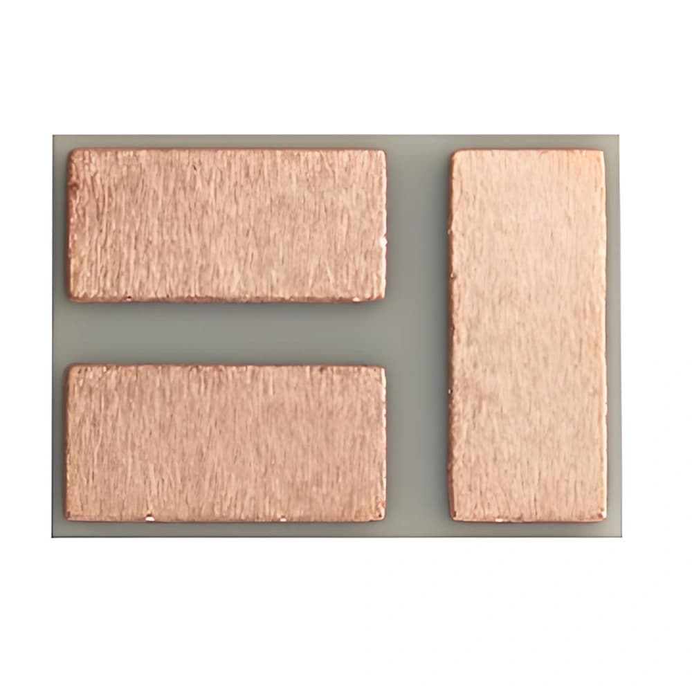
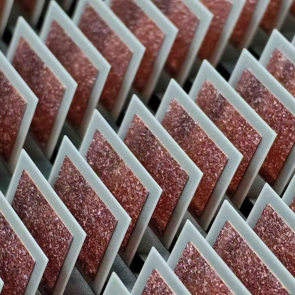
Si3N4 AMB copper-clad substrates positioned for high-reliability power modules and repeated thermal cycling.
Browse Products
Alumina Ceramic Products
Zirconia Ceramic Products
Silicon Carbide Products
Silicon Nitride Products
Aluminum Nitride Products
Product Description

Silicon nitride AMB substrates are copper-and-ceramic circuit carriers for power modules exposed to repeated temperature changes.
Active metal brazing joins the copper conductors to a mechanically strong, electrically insulating Si3N4 layer. Copper coverage, the braze interface and ceramic geometry work together in the finished construction.
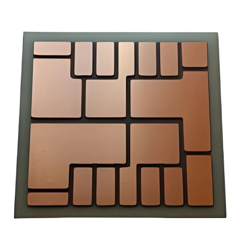
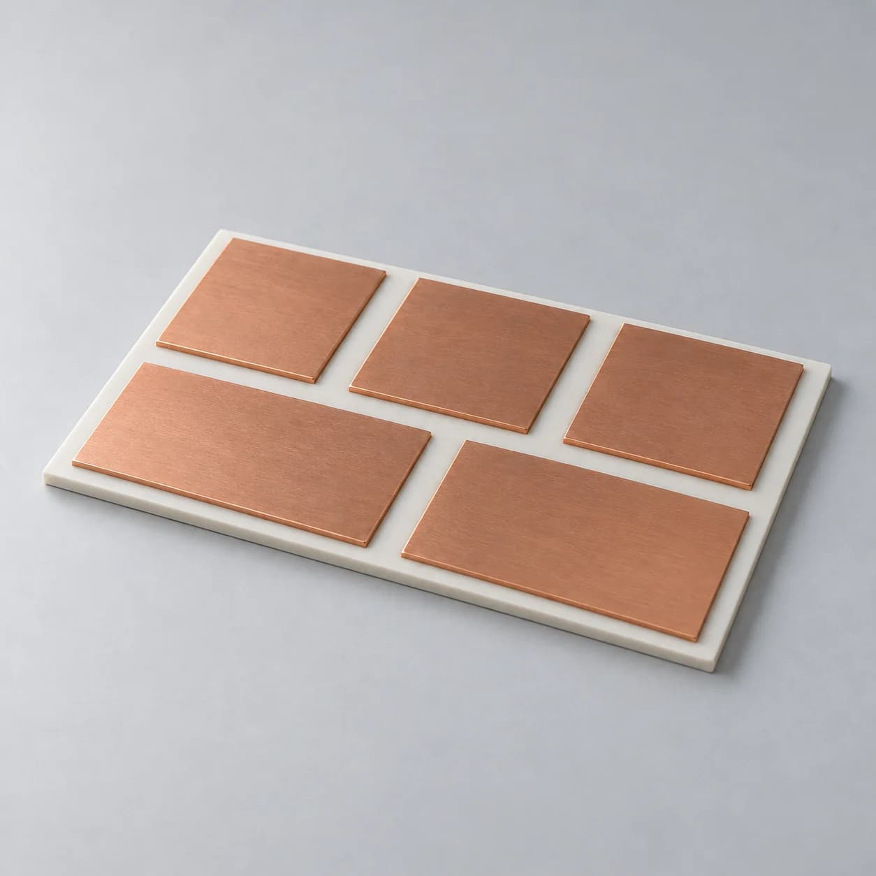
The illustration represents copper on Si3N4. AMB construction, copper thickness and thermal-cycling acceptance are confirmed for the selected design.
Product Advantages
- Active-metal-brazed copper supplies circuit conductors and attachment surfaces.
- The Si3N4 layer combines mechanical support with an electrically insulating heat path.
- A joined copper/ceramic construction supports coordinated front- and rear-side circuit functions.
Typical Applications
- Automotive Inverters: Si3N4 AMB substrates carry semiconductor devices and power interconnections.
- High-Reliability Power Modules: the substrate integrates copper circuitry with ceramic insulation.
Technical Data
Si₃N₄ Substrate (Sinalit) Properties
| Property | Sinalit — bare Si₃N₄ substrate | Conditions / ±10% measurement tolerance (except ref.) |
|---|---|---|
| Density (g/cm³) | ≥3.22 | DIN EN 993-1 |
| Bending strength (MPa) | ≥700 | — |
| Fracture toughness (MPa·m½) | ≥6.5 | Indentation-fracture method |
| Thermal conductivity (W/(m·K)) | 90 | Room temperature; DIN EN 821-2 |
| Coefficient of thermal expansion (10⁻⁶/K) | 3.3 (ref.) | 100–800°C; DIN 51045-1 |
| Dielectric strength (kV/mm) | ≥25 | 20°C; AC / DC; DIN EN 60243-1 |
| Volume resistivity (Ω·cm) | ≥10¹⁴ | Room temperature; IEC 62631-3 |
| Young’s modulus (GPa) | ≥280 | ASTM C1259-15 |
| Specific heat capacity (J/(g·K)) | ≥0.68 | 25°C; DIN EN 821-3 Method B |
| Relative permittivity | 7.8 (ref.) | Room temperature; 1 MHz; Ra ≤0.4 µm; ASTM D150 |
| Dielectric loss tangent | ≤0.003 | Room temperature; 1 MHz; Ra ≤0.4 µm; ASTM D150 |
Typical Construction Parameters
| Construction item | Typical configuration | Applicable condition |
|---|---|---|
| Ceramic base | Silicon nitride (Si3N4) | Grade and route dependent |
| Si3N4 thickness | 0.25 / 0.32 mm | Si₃N₄ ceramic layer |
| Copper thickness | 0.30 / 0.40 / 0.50 / 0.80 mm | Selected AMB layer combinations |
| Pattern | Custom power circuit | Drawing review required |
| Surface finish | Bare Cu and selected plated finishes | Assembly-process dependent |
How to Read the Parameters
- Bond strength
Peel force per width in N/mm differs from bond stress in MPa.
Specify: Test mode, fixture, specimen, rate and failure location.
- Thermal conductivity
A stated ceramic value is not an effective AMB-stack conductivity.
Specify: Ceramic grade, temperature and method.
- Thermal cycling
A cycle count applies only to its defined construction and profile.
Specify: Endpoints, dwell, ramp/transfer, samples, inspection and failure criteria.
- Layer and panel dimensions
Available combinations cannot be inferred from separate maximum values.
Specify: Complete stack, usable circuit area, outline and finished shape.
AMB: ceramic, braze and copper as one construction
AMB joins copper and ceramic through an active braze system whose reactive elements enable bonding at the ceramic interface. Ceramic grade, braze and copper geometry must be assessed together; generic AMB principles do not establish any one product’s numerical capability.

Application Conditions & Design Review
Preserve mechanical margin through the layout
Si3N4 offers a useful combination of substrate strength and thermal properties. Copper distribution, ceramic edges and assembly support still need review because the finished stack behaves differently from the bare ceramic.
Specify the bonding interfaces
Include the braze system, copper finish and intended component-attachment process. Avoid treating a copper-clad blank and a finished patterned substrate as interchangeable deliverables.
Ceramic choice
Si3N4, AlN and selected alumina configurations address different thermal and mechanical priorities.
Copper distribution
Layer thickness and copper coverage influence current paths, heat spreading and thermomechanical stress.
Mission profile
Define operating temperatures and loading before choosing substrate and assembly qualification tests.
Send With Your Drawing
- Si3N4 grade and ceramic/copper layer thicknesses.
- Blank or patterned supply state, copper coverage, edge margins and surface finish.
- Joining, mounting and operating conditions with the required test scope.
Include the drawing revision, sample and production quantities, and required inspection documents.
Define Acceptance Before Production
- Inspect shape, copper pattern and agreed ceramic-edge/interface criteria.
- Define bond integrity and isolation tests, then qualify representative assembled stacks.
Agree the test methods, sampling plan, acceptance limits and required reports before production.
Available Forms & Processing
Product-specific geometry and processing features.
- Si3N4, braze system and copper layers identified as a complete construction.
- Top and bottom copper patterns, edge clearance and copper balance defined independently.
- Substrate-cycle conditions kept separate from the completed module power-cycle profile.
Engineering Questions
Why specify the copper pattern when selecting the ceramic?
Copper coverage and thickness affect heat spreading and the mechanical response of the joined stack. Review them with the ceramic thickness and the assembly rather than independently.
Is the active braze the same as component-attach solder?
No. The active braze is part of the ceramic-to-copper joining system. Die-attach solder or sinter material belongs to a later assembly interface.
Can one AMB product’s cycle result be used for another stack?
Not without evidence. Ceramic grade, braze, copper geometry, layer thicknesses and the test profile must be comparable.
Packaging & Shipping
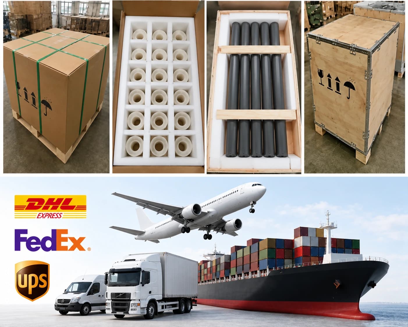
Packaging is selected for master cards, individual units and copper surface condition.
| Item | Details |
|---|---|
| Packaging approach | Packaging is selected for master cards, individual units and copper surface condition. |
| Protection methods | Individual separation; Anti-scratch surface protection; Rigid trays or master-card frames; Copper corrosion protection where appropriate; Inner box and export carton; Wooden case when required |
| MOQ reference | 5 pieces or one master-card equivalent |
| Lead-time references | AMB: 6-10 weeks |
| Payment terms | T/T / Western Union / PayPal; 50% advance payment, 50% balance before shipment |
| Shipping methods | Sea freight / Air freight / Door-to-door courier |
Related Ceramic Substrate Products
Compare related ceramic substrate materials and metallization routes within the same product family.