Laser-Scribed Alumina Substrates for Circuit Panels
Ceramic Substrate
SKU: FWM/CS-ALU-004
- Material
- Alumina
- Size
- Custom sizes by drawing
- MOQ
- By quotation
- Applications
- Integrated Circuits
96% alumina substrates with controlled laser scribing for circuit-panel separation and integrated-circuit production.
Browse Products
Alumina Ceramic Products
Zirconia Ceramic Products
Silicon Carbide Products
Silicon Nitride Products
Aluminum Nitride Products
Product Description

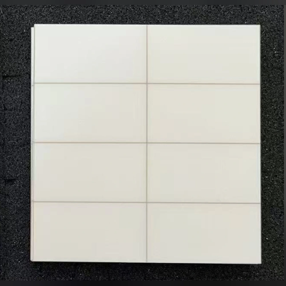
Laser-scribed alumina substrates hold multiple circuit positions in one panel during processing, with shallow scribe lines defining the later separation paths.
Panel-level handling supports circuit printing and assembly before singulation. The scribe lines are mechanical features, not conductive traces or full-depth cuts.
Scribing is a shallow separation feature, not a deep groove or a printed circuit. Panel layout and singulation requirements follow the drawing.
Product Advantages
- Scribed panels keep individual circuit positions together during printing and assembly.
- Defined separation paths organize subsequent singulation around the circuit layout.
- Panel datums connect circuit registration with the final piece geometry.
Typical Applications
- Integrated Circuits: panel processing precedes separation into individual ceramic carriers.
- Hybrid Circuits: scribe layouts organize multiple circuit positions on one panel.
Technical Data
96% Alumina Substrate (708 S) Properties
| Property | 96% Al₂O₃ — 708 S | Test conditions / measurement tolerance ±10% |
|---|---|---|
| Density (g/cm³) | ≥3.75 | DIN EN 993-1 |
| Bending strength, σ₀ (MPa) | ≥500 | — |
| Young’s modulus (GPa) | ≥300 | — |
| Thermal conductivity (W/(m·K)) | 24 | Room temperature; DIN EN 821-2 |
| Linear thermal expansion coefficient (10⁻⁶/K) | 7–9 | 100–800°C; DIN 51045-1 |
| Specific heat capacity (J/(g·K)) | ≥0.75 | 20°C; DIN EN 821-3 method B |
| Relative permittivity | ~9.8 | Room temperature, 1 MHz; Ra ≤0.4 µm |
| Dielectric loss factor | ≤0.005 | Room temperature; 1 MHz; Ra ≤0.4 µm |
| Volume resistivity (Ω·cm) | ≥10¹⁴ | Room temperature; IEC 62631-3 |
| Breakdown strength (kV/mm) | AC≥15; DC≥15 | 20°C; AC / DC |
| Fracture toughness (MPa·m½) | ≥3.0 | Indentation-fracture (IF) |
How to Read the Parameters
- Scribe geometry
A scribe is a partial-depth separation feature, not a finished cut edge.
Specify: Pattern, depth basis, placement and applicable process review.
- Finished unit size
The separated unit is the functional product geometry.
Specify: Final dimensions, edge allowance and measurement method.
- Panel robustness
Handling needs apply before separation as well as after it.
Specify: Processing sequence, support and premature-break criteria.
- Edge quality
Post-separation chipping and local defects need agreed limits.
Specify: Inspection magnification, critical regions and acceptance definition.
Laser scribing: controlled panel separation
Laser scribing creates intended separation paths in a ceramic panel. It differs from full-depth cutting, and the design must address both panel handling before separation and edge condition afterward.
01Define the panel array
Set unit outlines, circuit keep-outs and the intended separation sequence.
02Review the scribe pattern
Consider scribe directions, intersections and the material remaining before separation.
03Maintain the process panel
Keep the panel sufficiently supported for its specified downstream processing and handling.
04Separate and inspect
Evaluate final unit dimensions and edges after the agreed separation operation.
Application Conditions & Design Review
Keep panel processing and separation aligned
Scribed panels allow multiple circuit positions to remain together during processing. The scribe layout should match the intended break sequence and the edge requirements of the finished pieces.
Protect functional features
Leave drawing-defined separation margins between scribe lines and conductors, bond pads or holes. A controlled break path should not be assumed to produce the same edge as a fully cut outline.
Separation order
Plan how rows and individual parts will be separated without damaging circuits.
Circuit protection
Identify keep-outs and sensitive features near scribe lines and intersections.
Delivery form
Specify intact panels, partially separated arrays or individual pieces.
Send With Your Drawing
- Panel map, final piece size, scribe pitch and reference datums.
- Required groove or perforation geometry, residual web and separation direction.
- Circuit keep-outs, downstream process sequence and allowable edge chipping.
Include the drawing revision, sample and production quantities, and required inspection documents.
Define Acceptance Before Production
- Verify scribe location and agreed depth or residual-web criteria.
- Evaluate sample separation and finished edges before approving a panel layout.
Agree the test methods, sampling plan, acceptance limits and required reports before production.
Available Forms & Processing
Product-specific geometry and processing features.
- Panel maps with piece outline, scribe pitch and reference datums.
- Scribe depth or residual web, separation direction and circuit keep-outs defined as distinct features.
- Shallow mechanical separation features rather than conductive traces or full-depth cuts.
Engineering Questions
Does laser scribing create the electrical circuit?
Not by itself. Here scribing defines mechanical separation features in the ceramic. Conductive traces require a separately specified metallization process.
Is a laser-scribed substrate already cut into individual parts?
Not necessarily. Scribing leaves planned break paths; the required delivery and separation state must be specified.
Why specify the break sequence?
Scribe directions and panel handling affect how the array separates. Defining the sequence helps align edge quality and circuit protection with the intended process.
Packaging & Shipping
Packaging is selected for substrate finish, quantity and export handling.
| Item | Details |
|---|---|
| Packaging approach | Packaging is selected for substrate finish, quantity and export handling. |
| Protection methods | Individual separation; Anti-scratch interlayers for polished surfaces; Tray or foam protection; Inner box and export carton; Moisture protection where appropriate; Wooden case for larger export consignments when required |
| MOQ reference | By quotation |
| Lead-time references | Quotation inputs: Drawing, material, finish, quantity and delivery destination |
| Payment terms | T/T / Western Union / PayPal; 50% advance payment, 50% balance before shipment |
| Shipping methods | Sea freight / Air freight / Door-to-door courier |

Related Ceramic Substrate Products
Compare related ceramic substrate materials and metallization routes within the same product family.