Aluminum Nitride Ceramic Substrates for IGBT Modules
Ceramic Substrate
SKU: FWM/CS-ALN-005
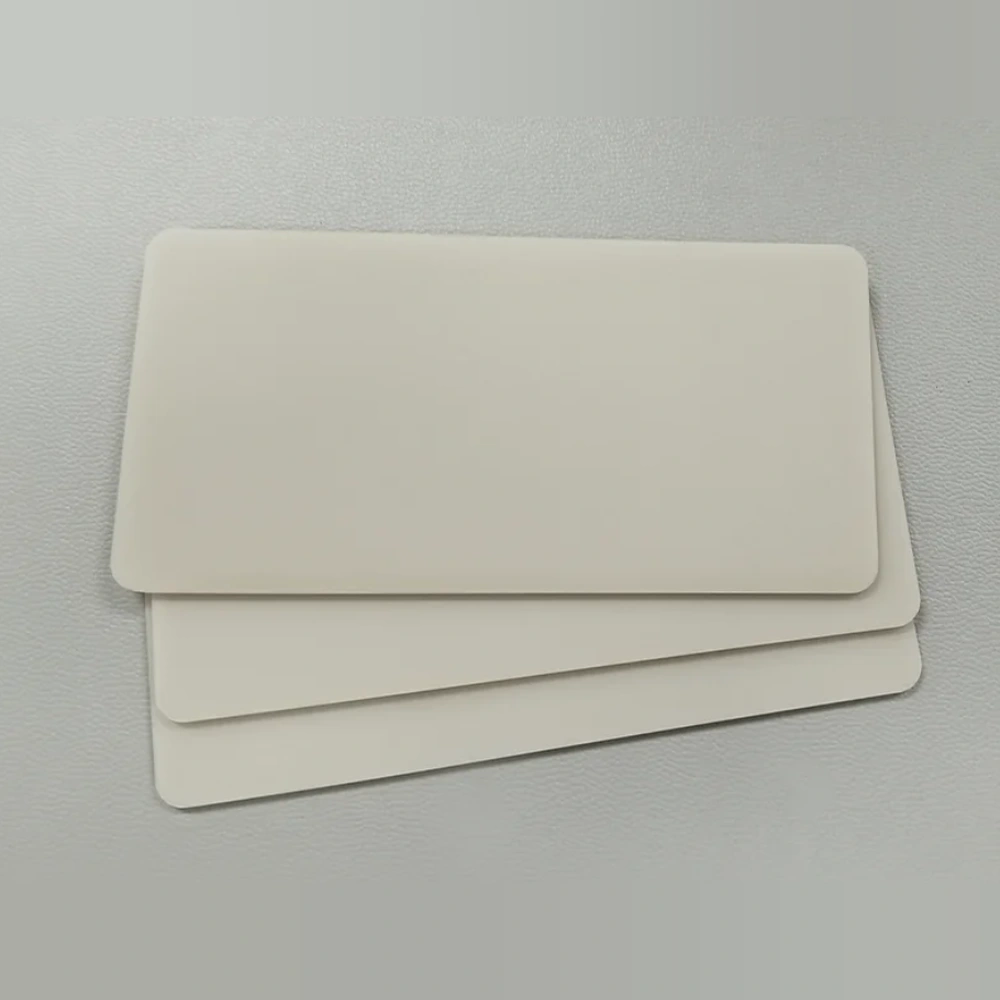
- Material
- Aluminum Nitride
- Size
- Custom sizes by drawing
- MOQ
- By quotation
- Applications
- IGBT Power Modules
AlN substrates for electrically insulated heat transfer in IGBT power-module assemblies.
Browse Products
Alumina Ceramic Products
Zirconia Ceramic Products
Silicon Carbide Products
Silicon Nitride Products
Aluminum Nitride Products
Product Description

AlN substrates provide the electrically insulating ceramic heat path beneath IGBT power circuits.
They transfer device heat toward the cooling structure while supporting a subsequent copper or other metallization system. The bare ceramic is not a finished power circuit; module performance includes the conductors, attachment layers and cooling interfaces.
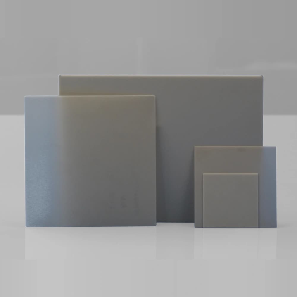
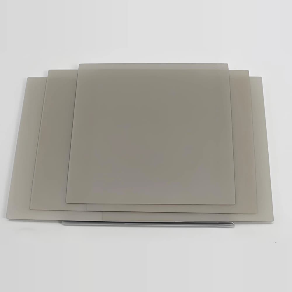
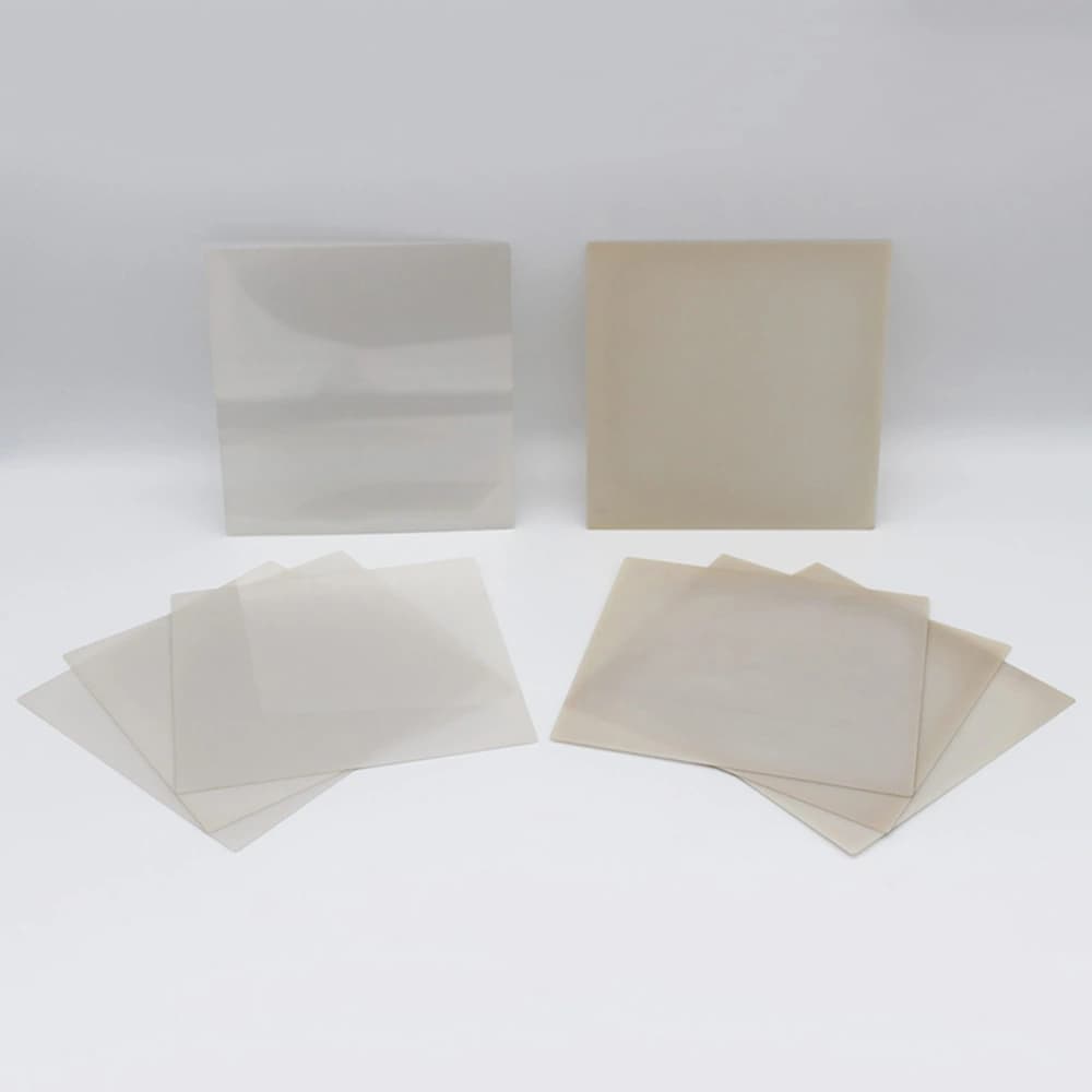
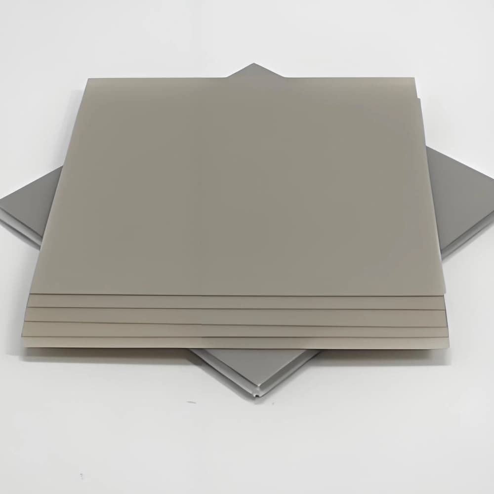
Bare AlN is shown; an application name does not imply an included circuit or copper cladding. Confirm the downstream circuit and assembly process.
Product Advantages
- AlN provides an electrically insulating heat path beneath power-device circuitry.
- A rigid ceramic carrier supports subsequent copper or other conductor attachment.
- Custom plate geometry links the device footprint with the cooling interface.
Typical Applications
- IGBT Power Modules: bare AlN supplies the insulating ceramic layer for a subsequent circuit stack.
- Power Inverters: ceramic carriers transfer heat toward the module mounting structure.
Technical Data
95% AlN Substrate Properties
| Property | 95% AlN typical value | Condition / method |
|---|---|---|
| AlN content (%) | 95 | — |
| Density (g/cm³) | ≥3.3 | — |
| Flexural strength (MPa) | ≥400 | — |
| Thermal conductivity (W/(m·K)) | ≥170 | Room temperature |
| Relative permittivity | 8–10 | 1 MHz; room temperature |
| Dielectric loss tangent | ≤0.0003 | 1 MHz; room temperature |
| Dielectric strength (kV/mm) | 17 | — |
| Volume resistivity (Ω·cm) | ≥10¹⁴ | — |
How to Read the Parameters
- Thermal conductivity
A ceramic property in W/(m·K), not a complete-stack rating.
Specify: Grade, temperature, direction where relevant and method.
- Thermal resistance
A defined heat-path result in K/W.
Specify: Heat-source area, layer dimensions, interfaces and cooling boundary.
- Thermal expansion
CTE is expressed in ppm/K or ×10⁻⁶/K over an interval.
Specify: Temperature interval and whether the value describes ceramic or the effective stack.
- Surface and geometry
A high-conductivity grade does not determine roughness or flatness.
Specify: Functional faces, thickness variation and dimensional acceptance separately.
AlN: an insulating thermal path
Aluminum nitride is considered when ceramic heat transfer is a major constraint. Its bulk conductivity must be distinguished from the thermal resistance of the finished substrate and module.
01Define the thermal requirement
Identify the heat-source footprint, temperature target, cooling interface and intended conductor system.
02Select the AlN grade
Review ceramic conductivity and other material properties at the relevant conditions.
03Prepare the specified form
Choose the delivered bare, machined or surface-finished condition for subsequent processing.
04Validate the interfaces
Evaluate film or metallization compatibility, attachment and cooling interfaces as part of the full construction.
Application Conditions & Design Review
Identify the power-substrate stage
An AlN plate for an IGBT module is a ceramic starting point unless metallization is explicitly included. Specify the copper-bonding or other circuit route needed for the complete module.
Review operating stresses together
Device heat, isolation voltage and assembly expansion interact. Include the attachment method, copper geometry and cooling interface when evaluating the ceramic choice and qualification plan.
Heat path
Include ceramic thickness, copper, attachment layers and contact area in the thermal assessment.
Downstream process
Identify deposited films or printed pastes, firing atmosphere and chemical exposures before selecting the surface.
Finished delivery state
Distinguish an as-fired blank from a polished plate or an already metallized substrate.
Send With Your Drawing
- Bare or metallized supply state, AlN grade and substrate geometry.
- Device and conductor layout, die attach, interconnect and cooling construction.
- Operating voltage, thermal mission profile and required qualification tests.
Include the drawing revision, sample and production quantities, and required inspection documents.
Define Acceptance Before Production
- Check ceramic geometry and functional-surface acceptance before metallization or assembly.
- Define isolation, thermal-cycling and power-cycling requirements for the appropriate test article.
Agree the test methods, sampling plan, acceptance limits and required reports before production.
Available Forms & Processing
Product-specific geometry and processing features.
- AlN plate outline, thickness and usable device area defined together.
- Bonding-face flatness and surface condition matched to the selected joining route.
- Bare ceramic specifications separated from conductor-stack and completed-module qualification.
Engineering Questions
Are thermal cycling and power cycling interchangeable?
No. They apply different loading mechanisms to the assembly. Specify the test profile, monitored failure criteria and whether the test concerns the substrate or completed module.
Does high AlN conductivity guarantee a cooler module?
No. The benefit depends on ceramic thickness, heat-source area, attachment layers and heat rejection. Evaluate the complete heat path.
Can an alumina film process be transferred directly to AlN?
Not without review. Confirm that the paste or deposited stack, atmosphere, thermal cycle and cleaning chemistry are compatible with the selected AlN system.
Packaging & Shipping
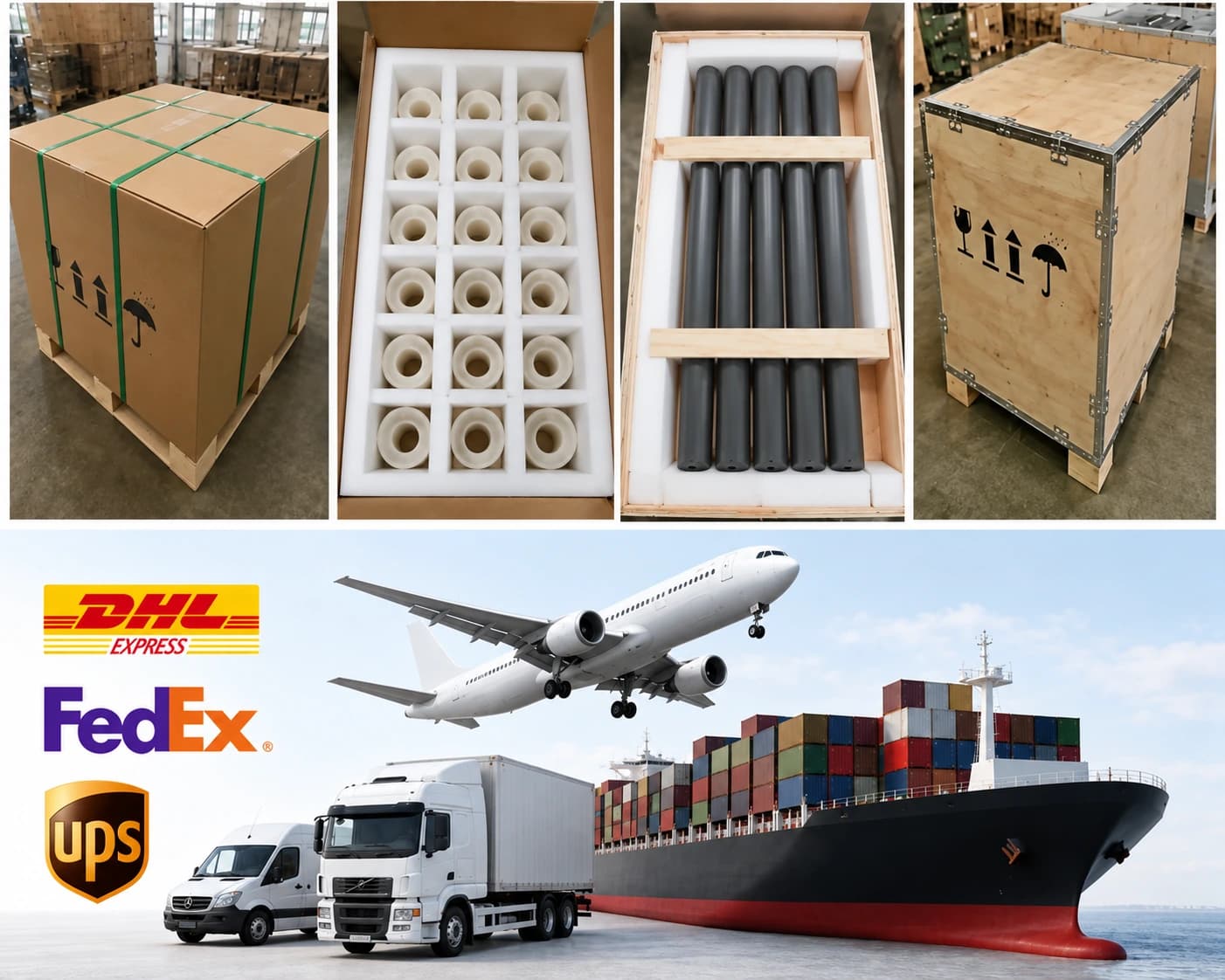
AlN substrates receive individual separation and surface protection appropriate to the finish.
| Item | Details |
|---|---|
| Packaging approach | AlN substrates receive individual separation and surface protection appropriate to the finish. |
| Protection methods | Individual separation; Anti-scratch interlayers; Rigid trays or foam protection; Moisture protection where appropriate; Inner box and export carton; Wooden case when required |
| MOQ reference | By quotation |
| Lead-time references | Quotation inputs: Drawing, material, finish, quantity and delivery destination |
| Payment terms | T/T / Western Union / PayPal; 50% advance payment, 50% balance before shipment |
| Shipping methods | Sea freight / Air freight / Door-to-door courier |
Related Ceramic Substrate Products
Compare related ceramic substrate materials and metallization routes within the same product family.