DPC Ceramic Substrates for Thermoelectric Coolers
Ceramic Substrate
SKU: FWM/CS-DPC-005
- Material
- Ceramic / Plated Copper System
- Size
- Custom sizes by drawing
- MOQ
- 10 pieces or one master-card equivalent
- Applications
- Thermoelectric Cooling
DPC metallized ceramic substrates for thermoelectric cooling-chip circuits and compact heat-management assemblies.
Browse Products
Alumina Ceramic Products
Zirconia Ceramic Products
Silicon Carbide Products
Silicon Nitride Products
Aluminum Nitride Products
Product Description

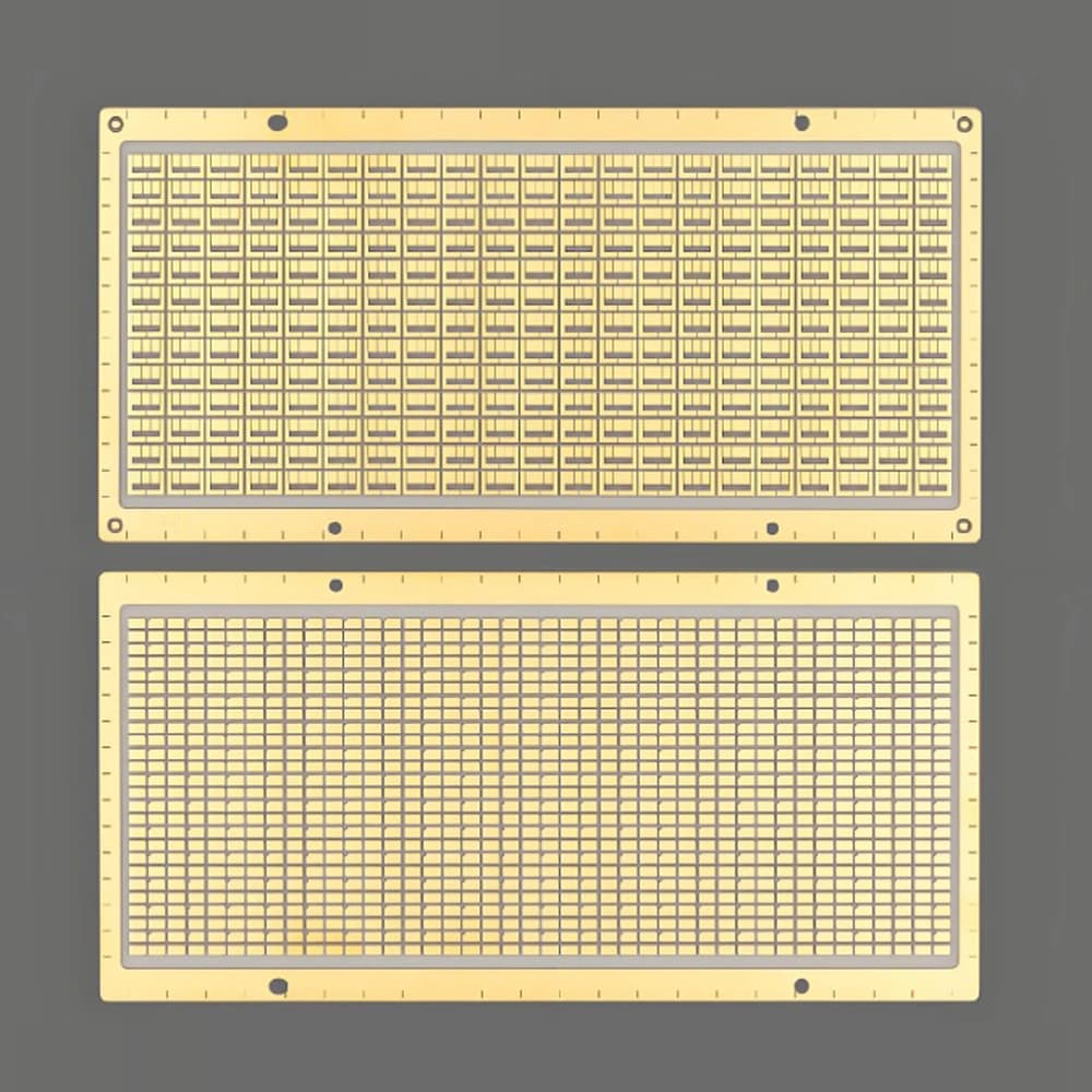
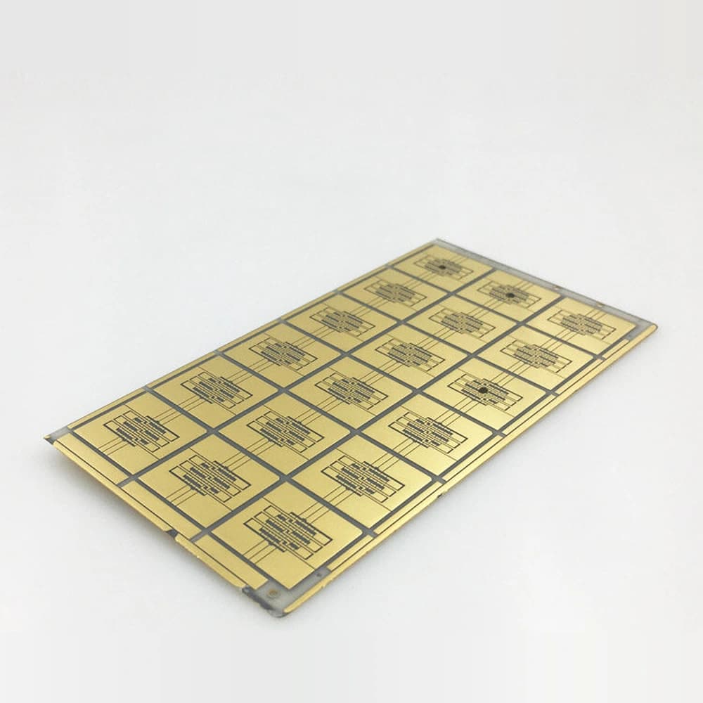
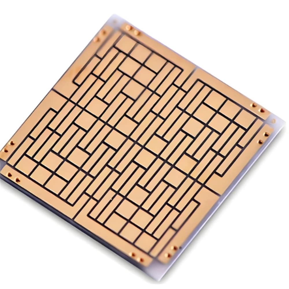
DPC ceramic substrates provide patterned electrodes and insulating support for thermoelectric cooling assemblies.
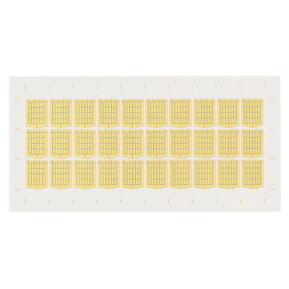
The copper layout connects the thermoelectric elements, and the ceramic provides the contact interface to the surrounding thermal assembly. The thermoelectric elements generate the cooling effect; the DPC substrate itself is not a complete cooler.
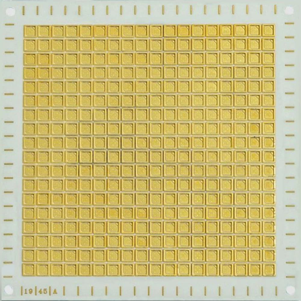
The image represents a thermoelectric electrode layout, not an assembled cooling module. Confirm ceramic base, copper pattern, finish and assembly requirements.
Product Advantages
- Plated electrode patterns connect thermoelectric elements across the ceramic carrier.
- The insulating ceramic separates live electrodes from the external thermal interfaces.
- Pattern registration connects electrode positions with module assembly geometry.
Typical Applications
- Thermoelectric Cooling: DPC electrode patterns support element interconnection and attachment.
- Cooling Modules: metallized carriers connect the electrical layout to external thermal-contact surfaces.
Technical Data
96% Alumina Substrate (708 S) Properties
| Property | 96% Al₂O₃ — 708 S | Test conditions / measurement tolerance ±10% |
|---|---|---|
| Density (g/cm³) | ≥3.75 | DIN EN 993-1 |
| Bending strength, σ₀ (MPa) | ≥500 | — |
| Young’s modulus (GPa) | ≥300 | — |
| Thermal conductivity (W/(m·K)) | 24 | Room temperature; DIN EN 821-2 |
| Linear thermal expansion coefficient (10⁻⁶/K) | 7–9 | 100–800°C; DIN 51045-1 |
| Specific heat capacity (J/(g·K)) | ≥0.75 | 20°C; DIN EN 821-3 method B |
| Relative permittivity | ~9.8 | Room temperature, 1 MHz; Ra ≤0.4 µm |
| Dielectric loss factor | ≤0.005 | Room temperature; 1 MHz; Ra ≤0.4 µm |
| Volume resistivity (Ω·cm) | ≥10¹⁴ | Room temperature; IEC 62631-3 |
| Breakdown strength (kV/mm) | AC≥15; DC≥15 | 20°C; AC / DC |
| Fracture toughness (MPa·m½) | ≥3.0 | Indentation-fracture (IF) |
99.6% Alumina Substrate (710 C) Properties
| Property | 99.6% Al₂O₃ — 710 C | Test conditions / measurement tolerance ±10% |
|---|---|---|
| Density (g/cm³) | ≥3.80 | DIN EN 993-1 |
| Bending strength, σ₀ (MPa) | ≥420 | ASTM C1499-08 |
| Young’s modulus (GPa) | ≥300 | — |
| Thermal conductivity (W/(m·K)) | ≥25 | Room temperature; DIN EN 821-2 |
| Linear thermal expansion coefficient (10⁻⁶/K) | 7–9 | 100–800°C; DIN 51045-1 |
| Specific heat capacity (J/(g·K)) | ≥0.65 | 20°C; DIN EN 821-3 method B |
| Relative permittivity | 8.5–11.5 | Room temperature, 1 MHz |
| Dielectric loss factor | ≤0.010 | Room temperature; 1 MHz; Ra ≤0.4 µm |
| Volume resistivity (Ω·cm) | ≥10¹⁴ | Room temperature; IEC 62631-3 |
| Breakdown strength (kV/mm) | AC≥15; DC≥15 | 20°C; AC / DC |
| Fracture toughness (MPa·m½) | ≥3.0 | Indentation-fracture (IF) |
95% AlN Substrate Properties
| Property | 95% AlN typical value | Condition / method |
|---|---|---|
| AlN content (%) | 95 | — |
| Density (g/cm³) | ≥3.3 | — |
| Flexural strength (MPa) | ≥400 | — |
| Thermal conductivity (W/(m·K)) | ≥170 | Room temperature |
| Relative permittivity | 8–10 | 1 MHz; room temperature |
| Dielectric loss tangent | ≤0.0003 | 1 MHz; room temperature |
| Dielectric strength (kV/mm) | 17 | — |
| Volume resistivity (Ω·cm) | ≥10¹⁴ | — |
Typical Construction Parameters
| Construction item | Typical configuration | Applicable condition |
|---|---|---|
| Ceramic base | 96% / 99.6% Al2O3 or AlN | Surface preparation dependent |
| Copper thickness | 10–130 µm | Plated thickness and pattern evaluated together |
| Line / space | Layout-dependent | Copper thickness, plating distribution and pattern geometry |
| Holes / vias | Laser holes and selected plated features | Aspect ratio and registration dependent |
| Surface finish | Ni/Au, Ni/Pd/Au or Ag examples | Finish stack matched to the attachment process |
How to Read the Parameters
- Copper thickness and line/space
Pattern feasibility depends on the finished copper thickness and geometry.
Specify: Thickness distribution, minimum gap, pad shape and registration basis.
- Surface condition
Bare ceramic, plated copper and pad finish are distinct surfaces.
Specify: Functional face, roughness parameter, cleanliness and finish composition/thickness.
- Resistivity and isolation
Volume resistivity uses Ω·cm or Ω·m; finished-circuit insulation resistance uses Ω.
Specify: Temperature, humidity, voltage, time and test geometry.
- RF material and circuit data
Permittivity and loss require frequency and test conditions.
Specify: Operating band, method, conductor stack and circuit-level acceptance.
- Adhesion
Peel in N/mm is not tensile or shear strength in MPa.
Specify: Test mode, geometry, rate, specimen preparation and failure location.
DPC: build and pattern the copper stack
DPC forms patterned copper on ceramic using an adhesion/seed stack, photolithography and electroplating. This substrate-metallization route is separate from any later functional thin-film processing, die attachment or package sealing.

How the substrate fits into a thermoelectric module

Application Conditions & Design Review
Build the electrode pattern around the TEC array
For thermoelectric cooling, the metallized substrate carries the connections between thermoelectric elements. Define the array and pad pattern so electrical connectivity and mechanical assembly agree.
Keep heat rejection in the system review
The substrate contributes thermal interfaces but is not the complete cooler. Flatness, pellet attachment and the hot-side cooling arrangement belong in the same design review.
Ceramic and copper
Select the ceramic grade and thickness with the plated-copper geometry and heat-source footprint.
Thin-film integration
Identify which resistor, conductor, dielectric or passivation layers will be added after DPC, and review their process compatibility.
Double-sided and via functions
Define each face and any vertical connections explicitly; rear copper does not imply through-hole connectivity.
RF requirements
Specify the operating band and finished-circuit requirements, not merely a low-frequency ceramic dielectric value.
Send With Your Drawing
- Thermoelectric element array and top/bottom electrode artwork.
- Ceramic and copper thicknesses, pad finish and attachment requirements.
- Hot/cold interface geometry, mounting arrangement and operating/test conditions.
Include the drawing revision, sample and production quantities, and required inspection documents.
Define Acceptance Before Production
- Verify electrode dimensions, connectivity and isolation to the agreed net map.
- Inspect functional interface geometry and qualify attachment and cooling at module level.
Agree the test methods, sampling plan, acceptance limits and required reports before production.
Available Forms & Processing
Product-specific geometry and processing features.
- Electrode pattern, ceramic grade, outline and thickness defined for the module.
- Copper thickness, solder or attachment finish and element-pad locations coordinated together.
- Front and rear flatness and parallelism defined at the module contact interfaces.
Engineering Questions
Does DPC metallization itself create the cooling effect?
No. Thermoelectric elements create the active heat-pumping effect. DPC provides patterned conductors on the ceramic carrier; module performance depends on the assembled system.
How should the DPC surface finish be selected?
Start with the attachment or downstream film process. Specify finish composition and thickness, pad areas, cleanliness and oxidation protection, then confirm compatibility with the intended soldering, bonding or deposition sequence.
Does a dielectric constant measured at 1 MHz prove microwave performance?
No. Use material data at relevant frequencies and evaluate the actual conductor geometry, finish, interconnections and completed circuit.
Packaging & Shipping
Packaging is selected for master cards, individual units and copper surface condition.
| Item | Details |
|---|---|
| Packaging approach | Packaging is selected for master cards, individual units and copper surface condition. |
| Protection methods | Individual separation; Anti-scratch surface protection; Rigid trays or master-card frames; Copper corrosion protection where appropriate; Inner box and export carton; Wooden case when required |
| MOQ reference | 10 pieces or one master-card equivalent |
| Lead-time references | DPC: 5-8 weeks |
| Payment terms | T/T / Western Union / PayPal; 50% advance payment, 50% balance before shipment |
| Shipping methods | Sea freight / Air freight / Door-to-door courier |

Related Ceramic Substrate Products
Compare related ceramic substrate materials and metallization routes within the same product family.