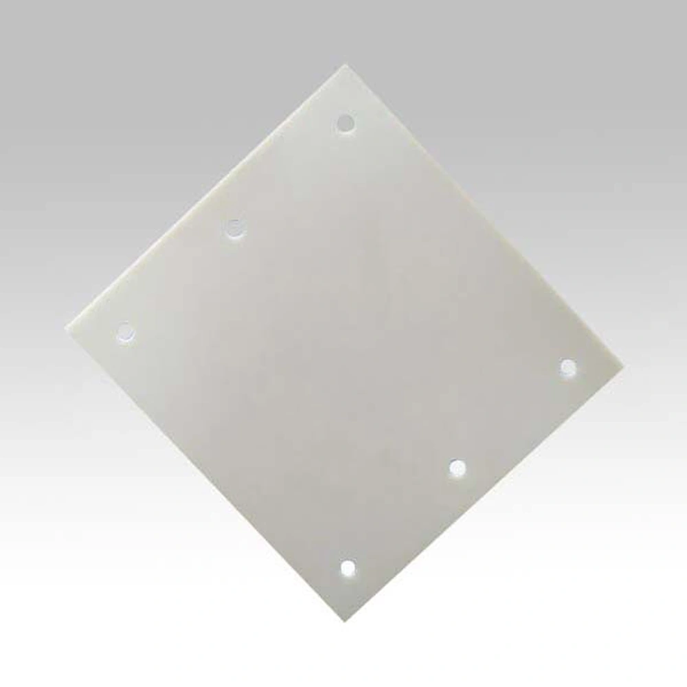
Drilled Aluminum Nitride Ceramic Substrates with Holes
Ceramic Substrate
SKU: FWM/CS-ALN-007
- Material
- Aluminum Nitride
- Size
- Custom sizes by drawing
- MOQ
- By quotation
- Applications
- Electronic Packaging
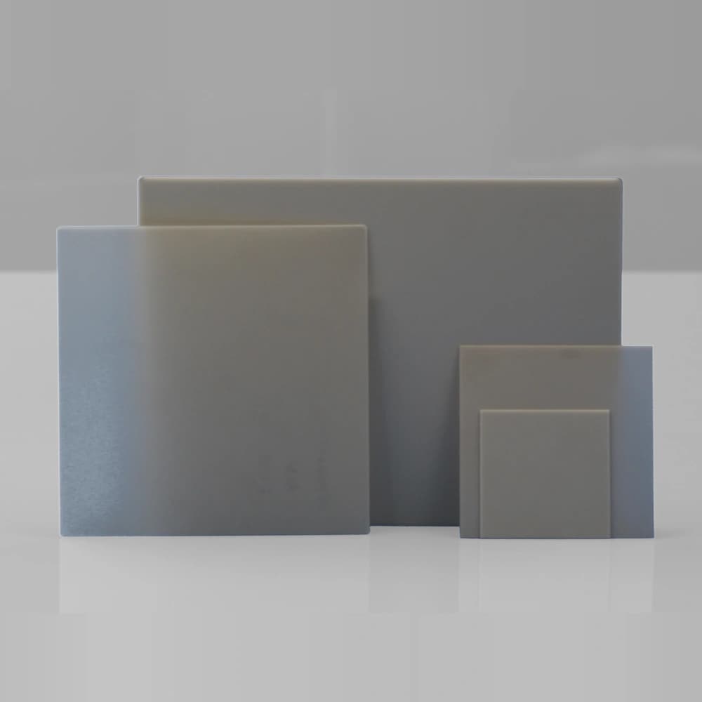
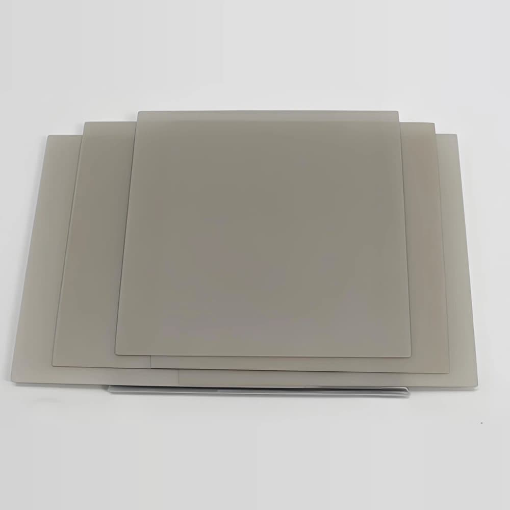
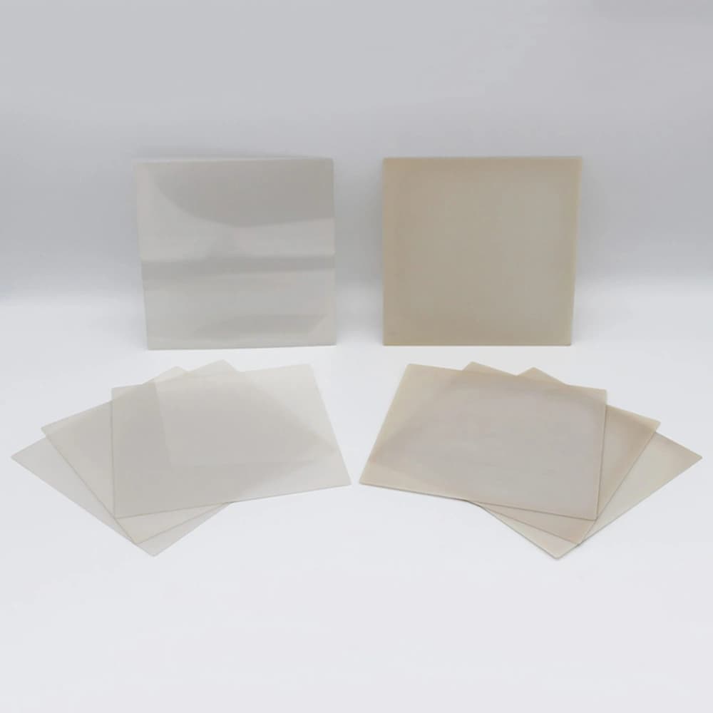
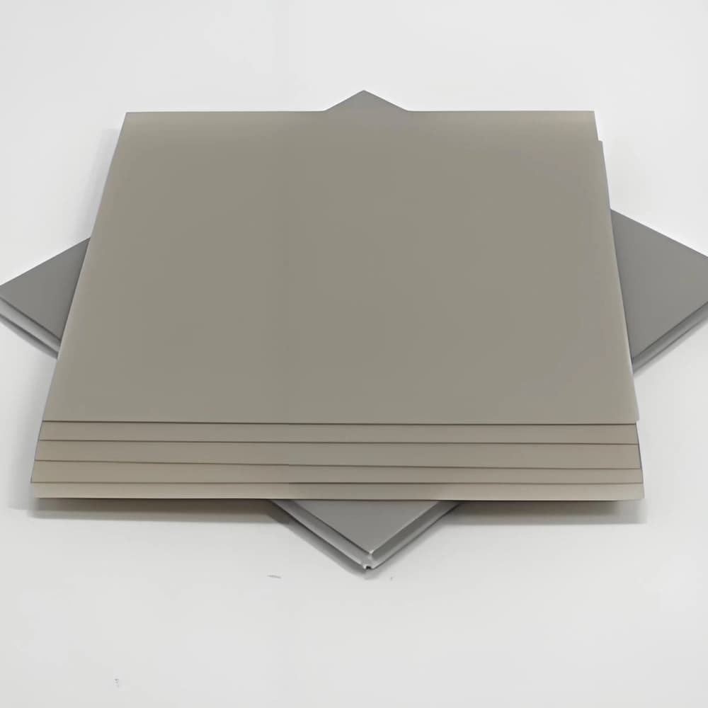
AlN substrates with drawing-defined holes for positioning, mounting and electronic packaging requirements.
Browse Products
Alumina Ceramic Products
Zirconia Ceramic Products
Silicon Carbide Products
Silicon Nitride Products
Aluminum Nitride Products
Product Description

Drilled AlN substrates incorporate openings for location, mounting and electronic-package integration while retaining an insulating heat-transfer path.
The holes align the ceramic with the surrounding assembly. A bare opening is not an electrical connection; conductive vias require a separate metallization or filling construction.
The illustrated holes are representative. Hole layout, mounting features and any other machining are supplied only as agreed in the approved drawing.
Product Advantages
- Drilled openings provide locating and mounting interfaces within an insulating carrier.
- The AlN body carries heat around the required package openings.
- A defined hole pattern connects substrate positioning to the surrounding assembly.
Typical Applications
- Electronic Packaging: openings locate the carrier or provide access through the ceramic.
- Power Devices: drilled insulating plates integrate with mounting and clearance features.
Technical Data
95% AlN Substrate Properties
| Property | 95% AlN typical value | Condition / method |
|---|---|---|
| AlN content (%) | 95 | — |
| Density (g/cm³) | ≥3.3 | — |
| Flexural strength (MPa) | ≥400 | — |
| Thermal conductivity (W/(m·K)) | ≥170 | Room temperature |
| Relative permittivity | 8–10 | 1 MHz; room temperature |
| Dielectric loss tangent | ≤0.0003 | 1 MHz; room temperature |
| Dielectric strength (kV/mm) | 17 | — |
| Volume resistivity (Ω·cm) | ≥10¹⁴ | — |
How to Read the Parameters
- Hole diameter
State the required finished size in mm or µm.
Specify: Measurement plane, entrance/exit requirements and tolerance.
- Position
Feature location is defined relative to agreed datums.
Specify: Datum scheme, positional tolerance and inspection method.
- Edge condition
Chips, local damage and transition features need explicit criteria.
Specify: Critical edges, allowable defect definition and inspection area.
- Metallized features
A laser hole alone is not an electrical connection.
Specify: Via construction, metal coverage, continuity and isolation requirements when applicable.
Drilled and machined features: geometry and edge control
Drilled and machined ceramics are defined by their finished features and functional surfaces. Specify the required geometry and acceptance criteria before selecting laser or other machining routes.
01Define each feature
Identify locating holes, mounting holes, slots, cut-outs and later metallization features.
02Review geometry and material
Assess ceramic thickness, feature position, spacing and proximity to critical edges.
03Process and prepare
The selected machining sequence creates the features; any cleaning or further finishing is specified for the material and subsequent process.
04Inspect the result
Measure the finished geometry and assess entrance, exit and edge condition against agreed criteria.
Application Conditions & Design Review
State what the hole must do
A locating pin, fastener or future metallized via places different demands on a drilled AlN opening. Specify the purpose and required engagement before setting the dimensions.
Include the exit face
Review hole geometry through the full plate thickness, including taper and exit-edge condition. A single top-view diameter is insufficient when fit or later metallization is important.
Feature function
Mechanical holes and electrically metallized vias have different requirements.
Thickness and geometry
Hole and slot feasibility depends on the ceramic, thickness and local layout.
Assembly datums
Locate features from the surfaces and datums that control the final assembly.
Send With Your Drawing
- Hole coordinates, datums, nominal dimensions and entrance/exit criteria.
- AlN grade, thickness, edge distances and any fit requirement.
- Hole function, subsequent metallization and allowable chips or cracks.
Include the drawing revision, sample and production quantities, and required inspection documents.
Define Acceptance Before Production
- Verify position, relevant diameters and taper against the drawing.
- Inspect sidewall and exit-edge condition; test continuity separately if metallization is supplied.
Agree the test methods, sampling plan, acceptance limits and required reports before production.
Available Forms & Processing
Product-specific geometry and processing features.
- Hole diameter, position, datum and edge distance defined for each pattern.
- Hole taper and entry/exit edge quality specified independently from nominal diameter.
- Bare openings kept separate from metallized or filled electrical-via constructions.
Engineering Questions
Is a drilled AlN hole a thermal or electrical via?
Not automatically. A bare hole has no metal conductor. Specify the filling or plating system and its purpose if a conductive path is required.
Can the same hole design be used for every ceramic thickness?
Not automatically. Review feature size, shape and edge condition with the selected material and thickness.
If laser drilling is selected, does it include plated-through holes?
No. Drilling defines the opening. Plating or another via conductor is a separate construction that must be specified and qualified.
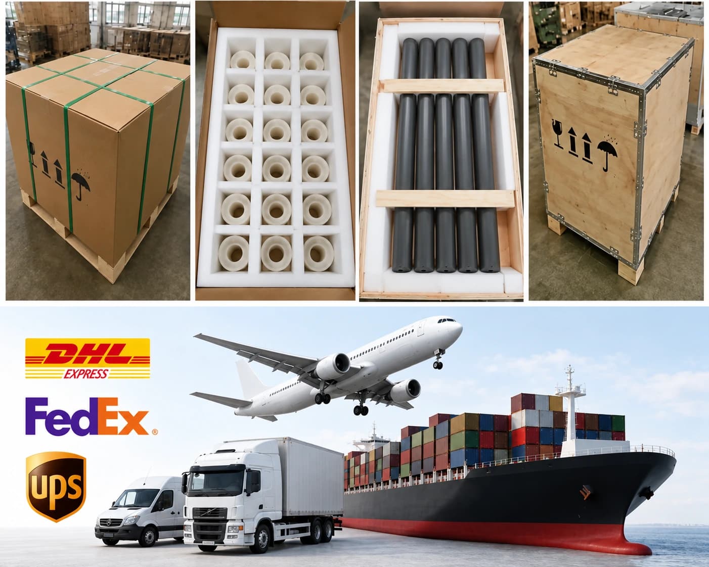
Packaging & Shipping
AlN substrates receive individual separation and surface protection appropriate to the finish.
| Item | Details |
|---|---|
| Packaging approach | AlN substrates receive individual separation and surface protection appropriate to the finish. |
| Protection methods | Individual separation; Anti-scratch interlayers; Rigid trays or foam protection; Moisture protection where appropriate; Inner box and export carton; Wooden case when required |
| MOQ reference | By quotation |
| Lead-time references | Quotation inputs: Drawing, material, finish, quantity and delivery destination |
| Payment terms | T/T / Western Union / PayPal; 50% advance payment, 50% balance before shipment |
| Shipping methods | Sea freight / Air freight / Door-to-door courier |
Related Ceramic Substrate Products
Compare related ceramic substrate materials and metallization routes within the same product family.